


19/4/13 - Expansion of the product portfolio
|
Let us introduce you the expansion of the product portfolio of our company about transformers of brand ABB. |
» Kámen Zbraslav, Paskov, Czech Republic
» OC Krakov + Billa, Czech Republic
» Areal ÚJV Řež, Czech Republic
» Třinecké železárny - injektáž, Czech Republic
» Adularya Enerji - Yunus Emre, Turkey
» Dalkia Ostrava - Šverma, Czech Republic
» Bauhaus Plzeň, Czech Republic
» Benteler Automotivve Rumburk, Czech Republic
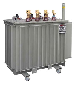
Dry cast resin transformers |
Suché zalévané transformátory tvoří významný podíl v nabídkovém portfoliu společnosti Power-Energo. Kvalitu dodávaných produktů zaručujeme spoluprácí s jedním z předních evropských výrobců transformátorů společností SEA, která vyvíjí a vyrábí suché zalévané transformátory již od roku 1975. Díky dlouhodobě získaným zkušenostem, technické erudovanosti pracovníků jakož i používaným konstrukčním programovým vybavením a moderní výrobní technologii, dokáže SEA splnit i ty nejnáročnější požadavky zákazníků.
| Output range: Rated voltage: Tapping on primary: Secondary voltage: Frequency: Vector group: Cooling: Winding conductor material: Isolation class: Protection degree transformer: Max. average temperature rise: |
50 ÷ 3 150 kVA up to 52 kV ±2x2,5 % (or other) 400 V (or other) 50 Hz Dyn1 AN (AF) Cu or Al F IP00 100/100 K Parameters and drawings |
 |
TTR transformers are three-phase dry transforms with high-voltage winding, cast in epoxy resin in a vacuum and they represent an alternative to traditional oil-immersed transformers. SEA manufactures and develops these transformers since 1975 and, due to their used design solution, unified components, and modern technology; they are among the leading European manufacturers in this field. TTR transformers are designed to satisfy the demands of all customers from standard up to special applications.
Magnetic core
The core is composed of grain-oriented magnetic sheets featuring high permeability and reduced specific losses, separated by inorganic insulation (carlite). The special cutting and assembly of the core allow for “STEP-LAP” joints which reduce noise as well as losses and the no load current. The magnetic sheets are pressed by galvanized core clamps. The core is insulated and varnished in an F temperature class.
Low voltage windings
The secondary coil consists of an electrolytic aluminum foil conductor interwound with an insulating film in pre-preg class “F”, then subjected to the oven drying process. The outlet terminals are aluminum bus bars welded in an inert atmosphere and firmly locked to the frame with spacer insulators.
This type of structure guarantees:
Copper windings or windings as per customer specifications are available on request.
Medium voltage windings
|
High voltage winding is carried out by automatic machines and consists of a set of electrolytic aluminum tape coils. The insulation between turns is obtained through a polyester film. The entire coil is framed by a glass fiber net, dried in depth and subsequently vacuum incorporated with a class F epoxy resin mixed with quartz and trihydrated alumina. This assures excellent mechanic sturdiness and compliance with classes C1 and C2 of the IEC rules. |
 |
|
Based on the manufacturer’s 30 years’ experience and the implementation of automatic devices (which control and record all the critical parameters of the process) we can guarantee extremely reduced partial discharges (about 5 pC), an essential requirement for the manufacture of quality, reliable and long-lasting coils. The adjustment links (generally ±2x2.5%) are obtained directly at the center of the coil. |
 |
Final assembly
Every transformer is tested in our test room with routine tests in compliance with IEC60076-11, i.e.:
At the customer’s request all type and special testings provided for by the rules may be carried out:
Archive of type tests
SEA has a large archive of type and special tests carried out on many resin transformers delivered to customers worldwide. The archive is available at all times for our customers to consult.
Room temperature and load conditions
The resin transformers from the TTR series have been designed to supply nominal power in a regular distribution network, the conditions of which are defined by IEC 60076-11 Standards. Heights over 1000 meters, room temperatures higher than 40 °C or specific network or load conditions (presence of overvoltages, harmonics, overloads…) place dielectric, mechanic or thermal stress on the transformer which has to be considered during the design process in order not to compromise its reliability and life.
|
Room dimensions Many components of the resin transformer may be easily touchable when the machine is operating. The same MV coils insulated with epoxide resin and the connections for closing the triangle circuit, generally insulated by a heat shrinkage tube, must be considered as “live parts”, thus the machine has to be properly segregated.
|
 |
|
The cell should allow for the proper exchange of air (at least 4.5 m3/minute of air for every kW of loss). The distance of the walls from the live parts should comply with the current local rules and in any case be shorter than those indicated in table 1. |
 |
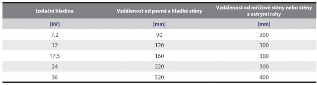
Tab 1
Protection enclosure
|
The transformer is generally delivered in a IP00 protection degree. At the customer’s request the transformer may be supplied with a cabinet for indoor installations featuring a protection degree in compliance with the customer’s specifications. In this case the cabinet itself protects the transformer from accidental contact. The installation room should in any case feature dimensions and distances as to ensure the proper exchange of air (there should be approximately 500 mm distance between the cabinet wall and the room wall, to allow for both proper air circulation and the regular inspection/maintenance of the transformers). |
 |
The type TTR dry transformers with standard operation provide for LV bus bars designed for top-side connections and bottom-side MV line connections. Connection instructions common practice for the installation technicians. We recommend properly supporting and connecting the bus bar and the connection cables so that their weight and most of all electrodynamic stresses due to a possible short circuit do not influence the transformer’s performance.
|
Special attention should also be given to the MV cable: the outermost insulation of cables shall be considered at ground potential, therefore must be kept at a certain distance from the transformer live parts in the same way as for the other accessories, in compliance with table 2. |
 |

Tab 2
TTR Transformers are three-phase dry transformers with englobed MV resin windings, which represent a valid alternative to the traditional oil-immersed transformers. SEA has been designing and producing this type of transformers since 1975, making itself one of the leading firms in the sector thanks to its construction solutions adopted, unification of details and to modern technologically advanced production facilities. SEA TTR transformers have been designed to satisfy our customers’ needs, from single users to large industrial groups, assuring:
The absence of inflammable liquids facilitates the plant engineer’s work, who can carry on the project more freely. This advantage is especially appreciated for those installations where operational safety is fundamental, for instance in hospitals, public premises, airports, subway lines, mines, oil platforms, nuclear plants, ships, etc…
SEA dry transformers comply with the IEC 60076-11 standards.
The construction based on other rules and/or standards may in any case be required and verified by our engineering and commercial department.
The standard catalogue covers up to 3150 kVA and 36 kV. Our design and construction capacity can satisfy the most diverse of needs (autotransformers, applications for converters, for traction, for testing rooms, etc…), with powers up to 25MVA.
Copyrigt © 2024 www.power-energo.cz | Power-energo s.r.o., Pod Pekárnami 245/10, 190 00 Praha 9 - Vysočany, IČ: 27456986 | Mapa | Partneři
Naše produkty: Trafostanice | Transformátory | Trafostanice skladem | Rozvaděče | Bioplynové stanice
